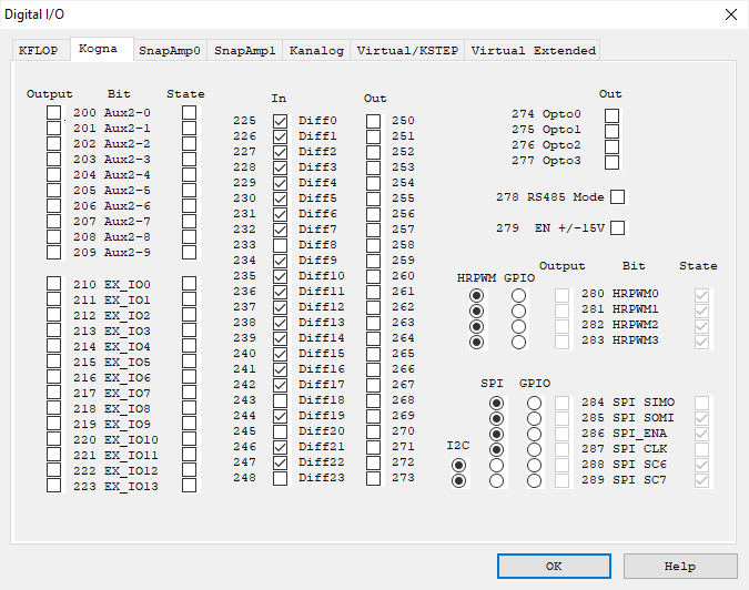
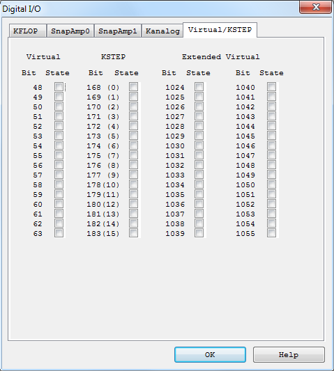
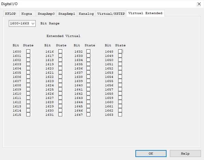
Digital I/O Screen


The Digital I/O Screen displays and allows changes to the current state of Kogna digital I/O bits. Digital IO bits are present on the Kogna as well as any additional option cards (such as with two SnapAmps or Kanalog as shown above) as well as Virtual Bits (simulated with memory). IO bits are numbered 0-2047.
Kogna has a number of digital I/O bits that may be used as GPIO (General Purpose Inputs or Outputs) or as specific dedicated functions (ie. encoder inputs). There are many bits that may be utilized as GPIO (bits 0 - 45). Some bits may be independently defined as either an input or an output. On Power UP Kogna defines all I/O as inputs by default. A bit may be configured as an output by checking the corresponding box in the "Output" columns where available. Alternately, the bits may be configured by a C program running within the KMotion (See SetBitDirection()) or by Script commands (See SetBitDirection) sent to the Kogna.
Kogna bits 0-15 are connected to the JP7 connector normally which may
be used by Kogna to connect to auxiliary option boards such as Kanalog. These bits
are available for User use if no option cards are requiring them in the system.
If they are used to communicate
to an option board care should be taken to not issue any User IO commands to
these bits.
Kogna bits 16 - 25 are connected to the Aux#0 connector
normally used as a high-speed communication bus to connect to auxiliary option
boards such as SnapAmps. These bits are available for User use if no
option cards are requiring them in the system.
If they are used to communicate
to an option board care should be taken to not issue any User IO commands to
these bits.
The State of each I/O bit may be observed in the corresponding checkbox under the "State" columns. If the bit is defined as an output, clicking on the "State" checkbox will toggle the bit. Alternately, the bits may be read, set, or cleared by a C program running within Kogna (See ReadBit(), SetBit(), ClearBit(), or SetStateBit()) or by Script commands (See ReadBit, SetBit, ClearBit, or SetStateBit) sent to Kogna.
Additionally, buffered commands may change the state of Digital I/O bits. Buffered I/O commands are I/O commands that are inserted into the coordinated motion buffer. When it is required that I/O bits be changed at exact times within a motion sequence, buffered I/O commands may be inserted into the motion buffer (see SetBitBuf, ClearBitBuf, and SetStateBitBuf). In this case the I/O commands occur when they are encountered within the motion sequence. The KMotion GCode interpreter allows buffered I/O commands to be inserted within motion sequences by using a special form of GCode comment (See buffered GCode Commands).
See the Kogna Hardware Connector Descriptions, SnapAmp Hardware Connector Descriptions, Kanalog Hardware Connector Descriptions, or KStep Hardware Connector Descriptions for which IO bits are connected to the various connectors on those optional boards.
Caution: Shorting High Voltage (greater than 3.3V or 5V depending on pin tolerance) to any Digital I/O bit will be likely to cause permanent board damage.
Digital I/O bits 46 and 47 are dedicated to the control of the two LED's on Kogna. These two outputs are configured as outputs and tuned on when Kogna powers up. The are available for use as User status if desired.
For other IO bits and any dedicated purposes or modes see the Kogna Connector documentation.