KStep - Connector Pinouts

J1 Motor Power

Motor power VBB from 12-48V may be applied through J1 or alternately through JR1. For applications that require more than 10A of supply current both of the GND and VBB connections should be used.
Caution: Voltage Clamp jumpers must be set to a Higher Voltage than the applied voltage.
Caution: If JR1 is connected to a PC Power Supply, 12V will be applied to VB.
J2 J3 J4 J5


Connect Stepper Motors to connectors J2 through J5. A Stepper Motor has two independent coils A and B.This should be verified with an Ohmmeter. Connect one motor coil across the A terminals and the other coil across the B terminals.
Caution: Cross wiring the motor terminals is likely to cause damage to KStep and/or the motor.
Voltage Clamping
KStep features a jumper programmable Voltage Clamping Circuit. Voltage spikes due to Regenerative Braking and other sources can potentially raise the supply voltage up to a level that can damage electronics including KStep or the power supply. Voltage Spikes may also cause a power supply to trip a fault and shut down. KStep's Voltage clamp can be used to avoid these problems. KStep's Voltage Clamp can be programmed for 4 different voltage levels. It is not possible to disable the Voltage Clamp but the clamping voltage level may be changed. With all jumpers removed the Voltage will be clamped at 49V. Each jumper added will reduce the Clamping voltage by 12V. The order of the jumpers is not important as each reduces the Voltage by the same amount (12V). This allows common supply voltages of 12, 24, 36, and 48V to be used.
Caution: Connecting a supply voltage higher than the clamping voltage will draw excessive current and is likely to cause damage to KStep or the Power Supply.
| Jumpers Installed | Example | Clamping Level |
|---|---|---|
| None | None | 49V |
| 1 | A | 37V |
| 2 | A+B | 25V |
| 3 | A+B+C | 13V |
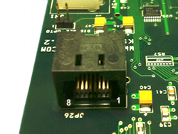
JP26

KStep can accept Step/Dir signals in from either JP26 or JP36 whichever is more convenient. Normally if two KSteps are connected to KFLOP/Kogna in order to have 8 axes in the system then JP26 will be used for the 2nd KStep. KFLOP/Kogna drives Step/Dir Generators 4 - 7 on its JP5 connector which when connected to KStep's JP26 connector will drive Motors 0 - 3. When driving signals into JP26 GND, +5V and Enable must be provided into KStep in some manner. J6 is usually the simplest but JR1 and JP36 are also possibilities.
| Pin | KFLOP/Kogna Name | KFLOP/Kogna Output | KStep Input |
|---|---|---|---|
| 1 | IO36 | Step 4 | Step 0 |
| 2 | IO37 | Dir 4 | Dir 0 |
| 3 | IO38 | Step 5 | Step 1 |
| 4 | IO39 | Dir 5 | Dir 1 |
| 5 | IO40 | Step 6 | Step 2 |
| 6 | IO41 | Dir 6 | Dir 2 |
| 7 | IO42 | Step 7 | Step 3 |
| 8 | IO43 | Dir 7 | Dir 3 |
Disable Optos Jumper
KStep normally drives JP36 pins 11 - 14 with selected Opto Input Data. If Opto Input Data is not desired this jumper disables this feature and leaves these pins in a high impedance state. This might be necessary if the connection to KFLOP/Kogna desires to use the associated pins for some other purpose such as KFLOP/Kogna Encoder inputs #2 and #3.
JR1
JR1 is a molex Disk drive type connector that can be used to provide Motor power (VBB) and +5V to KStep. Motor power is common to all 4 Motor Drives and may be applied either through JR1 or J1 screw terminals. A PC Power Supply often provides +5V on pin 4 and +12V on Pin 1 so caution should be made to assure different power supply voltages are not connected to both JR1 and J1. The +5V connection is used to power the Motor driver circuits. The +5V and GND connections are to the motor side of the isolation and will be isolated from the KFLOP/Kogna side if the Isolation Jumpers are removed.
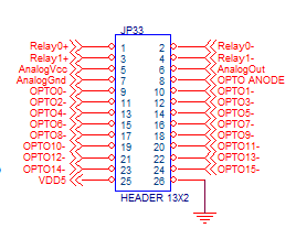
JP33

KStep adds 2 opto isolated relay drivers (100ma @ 36V), one Analog Output, and 16 opto isolated 12-24V inputs. All these IO are optically isolated regardless of the Isolation Jumpers set for the Isolation on the Step/Dir and enable signals. Opto Inputs have a common Anode normally connected to either +12V or +24V. Shorting any of the OPTO- pins to GND will activate the input. The Opto Inputs have a 10K ohm series resistance.

| JP33 Pin | KStep Signal | KFLOP/Kogna Related Signal |
|---|---|---|
| 1 | Relay0+ | IO 0 Output |
| 2 | Relay0- | IO 0 Output |
| 3 | Relay1+ | IO 1 Output |
| 4 | Relay1- | IO 1 Output |
| 5 | Analog Vcc | |
| 6 | Analog Out | IO 44 PWM Output |
| 7 | Analog Gnd | |
| 8 | Opto Anode | |
| 9 | Opto IN 0 | IO 168 Input |
| 10 | Opto IN 1 | IO 169 Input |
| 11 | Opto IN 2 | IO 170 Input |
| 12 | Opto IN 3 | IO 171 Input |
| 13 | Opto IN 4 | IO 172 Input |
| 14 | Opto IN 5 | IO 173 Input |
| 15 | Opto IN 6 | IO 174 Input |
| 16 | Opto IN 7 | IO 175 Input |
| 17 | Opto IN 8 | IO 176 Input |
| 18 | Opto IN 9 | IO 177 Input |
| 19 | Opto IN 10 | IO 178 Input |
| 20 | Opto IN 11 | IO 179 Input |
| 21 | Opto IN 12 | IO 180 Input |
| 22 | Opto IN 13 | IO 181 Input |
| 23 | Opto IN 14 | IO 182 Input |
| 24 | Opto IN 15 | IO 183 Input |
| 25 | Vdd +5V | +5V KFLOP (if non isolated) |
| 26 | GND KStep | GND KFLOP (if non isolated) |
Optically isolated Inputs
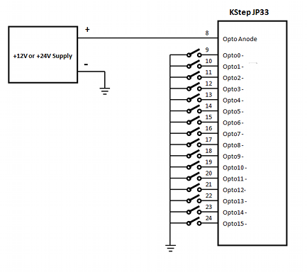
The input circuit for 4 of the 16 opto inputs is shown below. Note there is a common Anode for all 16 opto inputs which is normally tied to a +12 or +24V supply. Each of the negative opto pins are then switched to ground (return for the +12 or +24V supply).

External Wiring would typically be arranged such as:

Optically isolated PWM to Analog Circuit
A 3.3V PWM output from KFLOP/Kogna IO 44 JP7 pin 5 is normally connected to KStep JP36 Pin 5 to drive the PWM to Analog circuitry. Often a VFD will have 3 input terminals where a potentiometer can be connected as speed control. The three connections AnalogVcc, AnalogOut, and AnalogGnd can be connected to perform a similar function as a potentiometer. The AnalogOut voltage will vary from AnalogGnd to AnalogVcc voltage as a function of the PWM duty cycle.


Relay Driver Outputs
Two Optically Isolated Outputs are provided to drive medium power devices such as relay coils. Loads up to 30V @100ma may be driven.
The internal KStep circuitry is shown below which converts the incoming 3.3V LVTTL inputs to darlington transistor outputs.

A typical wiring diagram driving 24V relays.

JP31 JP32 PFD1 PFD2 Jumpers
These Jumpers can be used to control the Fast/Slow/Mixed delay settings of all 4 Motor Drives. In almost all cases these jumpers should remain removed for best performance.
Current Setting Jumpers
Current for each Stepper Coil is set with a set of 3 jumpers labeled H M L (high, medium, low).
Both sets of 3 jumpers for each motor coils must be set to the same level.
| H | M | L | Current (Amps) |
|---|---|---|---|
| Removed | Removed | Removed | 0.63 |
| Removed | Removed | Installed | 1.25 |
| Removed | Installed | Removed | 1.88 |
| Removed | Installed | Installed | 2.50 |
| Installed | Removed | Removed | 3.13 |
| Installed | Removed | Installed | 3.75 |
| Installed | Installed | Removed | 4.38 |
| Installed | Installed | Installed | 5.00 |
JP36 To KFLOP/Kogna

JP36 is designed to connect directly to KFLOP's/Kogna's JP7 in a 1:1 connection. KFLOP/Kogna is then able to supply the 4 sets of Step/Dir signals, the Enable, the Analog PWM signal, the 2 Relay Driver outputs, and connections for the 16 opto inputs, as well as +5V (used if running without opto isolation). To conserve KFLOP/Kogna IO pins, the 16 opto inputs are read back in a multiplexed fashion 4 bits at a time, where 2 outputs from KFLOP/Kogna select which bank of 4 are currently selected.+3.3V is also provided to power the opto multiplexing circuitry.

JP34 JP35 Isolation Jumpers
KStep allows all the Motor Power and +5V Mosfet circuitry to be totally optically isolated from the KFLOP/Kogna Step/Dir and Enable signals. To operate with total isolation remove JP34 and JP35. However in this mode an additional +5V supply must be provided and applied to either J6 or JR1. With the jumpers installed KStep will make use of KFLOP/Kogna +5V and KFLOP/Kogna GND coming in through connector JP36 and no additional supply will be required. The Block Diagram shows how the isolation is sectioned.
Regardless of these jumpers installed or not the 12-24V Optically isolated Inputs, the 2 Relay Driver outputs, and the Analog Output will always be fully optically isolated.
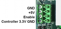
J6 - GND, +5V, Enable, 3.3V GND

J6 provides a connection point for +5V and GND to power the KStep Mosfet Drive Circuitry if operated in Isolated mode. The Enable connection allows a means of enabling KStep amplifiers if JP36 is not used to enable the amplifiers. Controller 3.3V GND is the same GND as on JP36 which is the KFLOP/Kogna or Controller Ground which is reference for the Step/Dir signals and Enable Signals. The Isolation Jumpers can be used to isolate or connect the two GND terminals on this connector.