SnapAmp - Connector Pinouts
SnapAmp contains three connectors labeled JP1, JP6, and JP7.
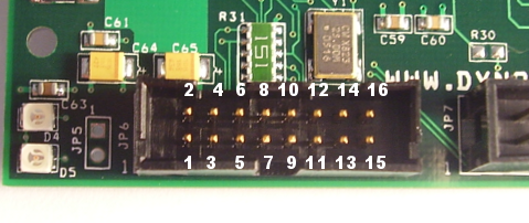
JP6 - KFLOP/Kogna Communication & Logic Power
JP6 is a proprietary high-speed communication bus where command and status communication between KFLOP/Kogna and the SnapAmp Amplifier. Up to two SnapAmps may be attached to a single KFLOP/Kogna. The second of the two SnapAmps must have a configuration jumper installed into JP5.
This connection is required for proper operation of the SnapAmp and should be as short as possible.

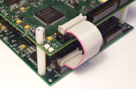
16 pin ribbon cable connection between SnapAmp and KFLOP/Kogna.
Note: 4 - 40 x 13/8 inch standoffs are used between SnapAmp (top) and KFLOP/Kogna (bottom).

16 pin ribbon cable connection between Dual SnapAmps and KFLOP/Kogna.
Notes:
4 - 40 x 1 3/8 inch standoffs are used between SnapAmp and KFLOP/Kogna.
4 - 40 x 1 5/8 inch standoffs are used between SnapAmps.
JP5 Jumper installed configures a SnapAmp as the 2nd SnapAmp.
When attaching SnapAmp to KFLOP/Kogna first attach main ground plug as shown.
For Dual Snap Amp systems attach the 1:2 spade Y adapter before connecting the first SnapAmp.
JP7 - I/O - General Purpose LVTTL - OPTO Isolated - Differential - Encoder Inputs
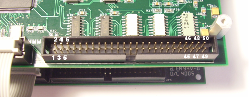
JP7 Is used for all Digital I/O. Fourteen General Purpose LVTTL I/O, Eight Differential Encoder Inputs, and Eight Optically Isolated Inputs.

Optically isolated input circuit. 5-12V may be applied. Current requirements at 5V is approximately 6ma and at 12V is approximately 20ma. SnapAmp Opto inputs have negative true polarity (energizing the Opto is read as a Logic 0 in KFLOP/Kogna).
| Pin | Name | Description | Bit SnapAmp #0 |
Bit SnapAmp #1 |
|---|---|---|---|---|
| 1 | GPIO0 | Gen Purpose LVTTL | 80 | 112 |
| 2 | GPIO7 | Gen Purpose LVTTL | 87 | 119 |
| 3 | GPIO1 | Gen Purpose LVTTL | 81 | 113 |
| 4 | GPIO8 | Gen Purpose LVTTL | 88 | 120 |
| 5 | GPIO2 | Gen Purpose LVTTL | 82 | 114 |
| 6 | GPIO9 | Gen Purpose LVTTL | 89 | 121 |
| 7 | GPIO3 | Gen Purpose LVTTL | 83 | 115 |
| 8 | GPIO10 | Gen Purpose LVTTL | 90 | 122 |
| 9 | GPIO4 | Gen Purpose LVTTL | 84 | 116 |
| 10 | GPIO11 | Gen Purpose LVTTL | 91 | 123 |
| 11 | GPIO5 | Gen Purpose LVTTL | 85 | 117 |
| 12 | GPIO12 | Gen Purpose LVTTL | 92 | 124 |
| 13 | GPIO6 | Gen Purpose LVTTL | 86 | 118 |
| 14 | GPIO13 | Gen Purpose LVTTL | 93 | 125 |
| 15 | CHA DIFF PLUS 0 | Differential Input + Encoder 0 Input Phase A | 64 | 96 |
| 16 | CHA DIFF MINUS 0 | Differential Input - Encoder 0 Input Phase A | 64 | 96 |
| 17 | CHB DIFF PLUS 0 | Differential Input + Encoder 0 Input Phase B | 65 | 97 |
| 18 | CHB DIFF MINUS 0 | Differential Input - Encoder 0 Input Phase B | 65 | 97 |
| 19 | CHA DIFF PLUS 1 | Differential Input + Encoder 1 Input Phase A | 66 | 98 |
| 20 | CHA DIFF MINUS 1 | Differential Input - Encoder 1 Input Phase A | 66 | 98 |
| 21 | CHB DIFF PLUS 1 | Differential Input + Encoder 1 Input Phase B | 67 | 99 |
| 22 | CHB DIFF MINUS 1 | Differential Input - Encoder 1 Input Phase B | 67 | 99 |
| 23 | CHA DIFF PLUS 2 | Differential Input + Encoder 2 Input Phase A | 68 | 100 |
| 24 | CHA DIFF MINUS 2 | Differential Input - Encoder 2 Input Phase A | 68 | 100 |
| 25 | CHB DIFF PLUS 2 | Differential Input + Encoder 2 Input Phase B | 69 | 101 |
| 26 | CHB DIFF MINUS 2 | Differential Input - Encoder 2 Input Phase B | 69 | 101 |
| 27 | CHA DIFF PLUS 3 | Differential Input + Encoder 3 Input Phase A | 70 | 102 |
| 28 | CHA DIFF MINUS 3 | Differential Input - Encoder 3 Input Phase A | 70 | 102 |
| 29 | CHB DIFF PLUS 3 | Differential Input + Encoder 3 Input Phase B | 71 | 103 |
| 30 | CHB DIFF MINUS 3 | Differential Input - Encoder 3 Input Phase B | 71 | 103 |
| 31 | OPTO NEG 0 | Opto Isolated Input 0 Negative Connection | 72 | 104 |
| 32 | OPTO POS 0 | Opto Isolated Input 0 Positive Connection | 72 | 104 |
| 33 | OPTO NEG 1 | Opto Isolated Input 1 Negative Connection | 73 | 105 |
| 34 | OPTO POS 1 | Opto Isolated Input 1 Positive Connection | 73 | 105 |
| 35 | OPTO NEG 2 | Opto Isolated Input 2 Negative Connection | 74 | 106 |
| 36 | OPTO POS 2 | Opto Isolated Input 2 Positive Connection | 74 | 106 |
| 37 | OPTO NEG 3 | Opto Isolated Input 3 Negative Connection | 75 | 107 |
| 38 | OPTO POS 3 | Opto Isolated Input 3 Positive Connection | 75 | 107 |
| 39 | OPTO NEG 4 | Opto Isolated Input 4 Negative Connection | 76 | 108 |
| 40 | OPTO POS 4 | Opto Isolated Input 4 Positive Connection | 76 | 108 |
| 41 | OPTO NEG 5 | Opto Isolated Input 5 Negative Connection | 77 | 109 |
| 42 | OPTO POS 5 | Opto Isolated Input 5 Positive Connection | 77 | 109 |
| 43 | OPTO NEG 6 | Opto Isolated Input 6 Negative Connection | 78 | 110 |
| 44 | OPTO POS 6 | Opto Isolated Input 6 Positive Connection | 78 | 110 |
| 45 | OPTO NEG 7 | Opto Isolated Input 7 Negative Connection | 79 | 111 |
| 46 | OPTO POS 7 | Opto Isolated Input 7 Positive Connection | 79 | 111 |
| 47 | VDD5 | + 5V Encoder Power Output | ||
| 48 | VDD5 | + 5V Encoder Power Output | ||
| 49 | GND | Digital Logic Ground | ||
| 50 | GND | Digital Logic Ground |
For a single page printable PDF of the above click here.
JP1 - Motor/Motor Supply (10-80V) Connector

| Motor type DC -Brush | Motor type - 3 Phase brushless | Motor type - Stepper | |
|---|---|---|---|
| Axis 0 | Connect Motor across OUT0-OUT1 Specify PWM Channel 8 |
Connect Phase A to OUT0 Connect Phase B to OUT1 Connect Phase C to OUT2 Leave OUT3 disconnected Specify PWM Channel 8 |
Connect Coil A across OUT0-OUT1 Connect Coil B across OUT2-OUT3 Specify PWM Channels 8 and 9 |
|
Axis 1 |
Connect Motor across OUT2-OUT3 Specify PWM Channel 9 |
||
| Axis 2 |
Connect Motor across OUT4-OUT5 Specify PWM Channel 10 |
Connect Phase A to OUT4 Connect Phase B to OUT5 Connect Phase C to OUT6 Leave OUT7 disconnected Specify PWM Channel 10 |
Connect Coil A across OUT4-OUT5 Connect Coil B across OUT6-OUT7 Specify PWM Channels 10 and 11 |
| Axis 3 | Connect Motor across OUT6-OUT7 Specify PWM Channel 11 |