Kanalog Hardware Info
From Dynomotion
Kanalog adds Analog and other I/O to KFLOP
| BlockDiagram | Board Layout |
| Kanalog Use and Settings |
Contents
- 1 Relay Drivers / Grounding
- 2 Logical "AND" of Opto Output and Relay Driver
- 3 Initial Setup/Testing for Analog Amplifiers
- 4 Configuring DAC and Encoder Channels
- 5 Max Output For DACs
- 6 Testing Analog Amplifiers
- 7 Drive Enables - Axis Drift with Servo Disabled - Power up Issues
- 8 Forum Threads on Setup and Tuning
Relay Drivers / Grounding
The 8 Relay drivers are open collector type (switch to GND) capable of switching loads up to 1Amp at up 24V. They share a common GND with Kanalog (are not isolated). The outputs on Kanalog are not guaranteed to power up off until after KFLOP has booted. The additional SWE relay driver should be used as a master enable to avoid momentary power up issues. SWE is guaranteed to remain off until after all the Kanalog Outputs have been initialized off.
Kanalog has a single GND common to KFLOP, control logic, relay drivers, and Analog signals. The GND should normally be isolated from Earth GND to avoid ground loops and injecting earth GND noise into Kanalog/KFLOP DC GND. Standoff mounting holes are completely isolated with the exception of the GND lug holes marked "GND".
The Opto Inputs and Outputs are fully isolated.
Logical "AND" of Opto Output and Relay Driver
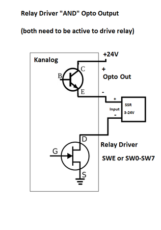
Both the Relay Driver and Opto Output need to be active to enable the Solid State Relay (SSR). Such a circuit can be used to assure a SSR remains off until after KFLOP Boots and SWE Relay Driver output goes active and KFLOP is initialized and the Opto Output is activated.
Note positions of the SSR and Opto Output may be reversed if desired. But because relay driver outputs are internally grounded it must be at the bottom.
Note a mechanical relay with coil may also be use but the coil should have a reverse diode across the terminals at the relay and the relay should draw less than 25ma (the limit of the Opto Output).

Initial Setup/Testing for Analog Amplifiers
There is a starting configuration for KFLOP+Kanalog called KanalogInitialPID.mot in the \KMotion\Motors folder. Load it into an axis channel from the KMotion Configuration Screen. The basic first steps are to verify the hardware:
- check the encoder counts correctly as shown on the KMotion Axis Screen Position (a KFLOP Axis must be configured as Encoder Input with the Input Channel0 set to the channel where the encoder is physically connected)
- check that the DACs can command the Amplifier to control motor speed. Test Console commands like DAC0=200 to Output ~ -1V (with the axis disabled - if any axis is enabled and continuously writing to the DAC any Console Command will be overwritten)
- If steps #1 and #2 above work correctly, enable the Servo using the Step Response Screen. Zero, Enable. The motor should then attempt to weakly hold position.
Configuring DAC and Encoder Channels
I think our software/documents some what over use the word channel which can confusion. There are Motor Axis Channels, DAC Output Channels, and Encoder Input Channels which are all different things. This diagram may help:
KFLOP Functional Diagram
Any KFLOP Motor Axis Channel can be configured to make use of any DAC or any Encoder by specifying the Input and Output channels. See:
Input Channels
The KanalogInitialPID.mot configuration file is an example of a Kanalog Axis using DAC #0 and Encoder #0. If simply loaded into multiple Motor Axis Channels it will configure all the Motor Axis to all use DAC 0 and Encoder 0 as their I/O devices.
So for example for the Second Motor:
- select Axis Channel #1
- load the KanalogInitialPID.mot configuration
- Change the Input Channel and Output Channel settings to the Encoder and DAC you want that motor to use (ie. #1 and #1)
Max Output For DACs
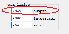
Note the Maximum Output range for the DACs is +/-2047 DAC Counts. Attempting to output larger values will cause a wraparound effect and runaway or following error fault. So set the Max Output to 2047 or less.

Testing Analog Amplifiers
One way to perform a basic test of an Analog Amplifier to see if it is working and likely capable of being driven by a Kanalog DAC Output is to apply a small voltage to the input to see if the motor drives. A 1.5V battery in series with a 1K Ohm resistor is one possible voltage source. The 1K Ohm resistor should limit the current in case a mistake is made. When applied the motor should drive at a controlled 15% (Speed if the drive is in Velocity mode, or torque if in torque mode). Reversing the battery should reverse the motor direction.
Drive Enables - Axis Drift with Servo Disabled - Power up Issues
Unlike digital values, analog values will always have some amount of noise and error on both inputs and outputs. This means that commanding Zero Volts is unlikely to be ever be exactly Zero and some small torque or drift will occur with Zero Volts commanded. The only way to guarantee no motor drive is to disable the Drive.
Kanalog is designed to be precise and linear but not highly accurate (+/- 1% components are used). Absolute accuracy on the servo output is not normally a requirement for good servo control. This is not a problem when the servo is enabled as the servo will command whatever output necessary to hold the desired position. However whenever the servo is disabled the Drive should also be disabled to avoid any motor drive or drift.
The Drive enable signals can be interfaced to KFLOP. Any I/O can be used as the Drive enables are handled in software as a User Program (see the watchenable.c example).
Often the Kanalog Relay Driver Outputs or Opto Isolated Outputs can be used for Drive Enables.
However please note that unfortunately the Kanalog Outputs Power up in an initially undetermined state for several seconds until KFLOP boots up. If this is a problem for your system then another means of keeping the Drives disabled should be used during initial power up. The Kanalog SWE Relay Output Driver is guaranteed to remain disabled until KFLOP fully boots and all Kanalog Outputs are initialized to the off state.
Forum Threads on Setup and Tuning
Anilam/ supermax Frankenstein project using Dynomotion Kflop and Kanalog boards
Tree325 Retrofit with KFLOP Kanalog (Thread includes .AVI Videos of User Tuning his system step-by-step)


