IIR Filter Screen
The IIR Filter Screen allows setting various IIR (Infinite Impulse Response) Filters into the control loop. KMotion allows up to three - 2nd order bi-quadratic stages per axis to be connected in cascade. See the KMotion Servo Flow Diagram for the placement of the IIR Filters.
KMotion implements the filters using Z-domain coefficients shown on the bottom half of the screen. Because of the common confusion of the names and signs of the coefficients, the transfer function form is shown for reference.

Note that setting B0=1.0 and all other coefficients, B1, B2, A1, and A2, to zero causes a transfer function of unity, effectively bypassing the filter. A Clear pushbutton is available to conveniently set this mode.

The top portion of each filter section allows various common filters to be specified in the s-domain. Supported filter types are: 1st order Low Pass, 2nd Order Low Pass, Notch, and two real poles and zeros and are selected using a drop-down list box.. Z-domain is a place holder used as a reminder that the z-domain coefficients were determined directly by some other means. The form of each of the filters in the s-domain is shown below.

If an s-domain filter type is selected and its corresponding parameters specified, then depressing the Compute pushbutton will convert the s-domain transfer function to the z-domain using Tustin's approximation (with frequency pre-warping) and automatically fills in the z-domain coefficients. Note that KMotion always utilizes the current (most recently computed or entered) z-domain coefficients, regardless of any changes that might be made to the s-domain section.
Note that the Bode Plot Screen has the capability to graph the combined transfer function of all three IIR filters and the PID filter. This is referred to as the Servo Compensation. To view the transfer function of a single IIR filter, set the other filter and PID sections to unity (for PID set P=1, I=0, D=0 or for an IIR Filter B0=1, B1= B2=A1=A2=0).
Below are examples of each of the s-domain filter types (shown individually):
Low Pass (1st order)
A Low Pass filter is commonly used in a servo system to reduce high frequency noise (or spikes) in the output. It also has the desirable effect of decreasing the gain at high frequencies. If a system's gain at high frequencies is increased sufficiently to reach 0 db it may become unstable. Unfortunately it has the effect of introducing phase lag (negative phase) which will reduce the phase margin. A 1st order Low Pass filter has 45 degrees phase and attenuation of -3db at the specified cutoff frequency. The cutoff frequency should normally be specified much higher than the servo bandwidth in order to have only a small phase lag at the system's bandwidth.
Low Pass (2nd order)
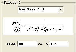
A 2nd order Low Pass filter is commonly used in a similar manner as a 1st order low pass filter, except that it has higher attenuation than a 1st order low pass filter. Unfortunately it also introduces more phase lag than a 1st order low pass filter. In most cases the cutoff frequency for a 2nd order low pass filter will have to be specified at a higher frequency than a 1st order filter, in order to have similar phase lag at the system bandwidth frequency. Even so, the 2nd order low pass filter is usually preferable in that it provides slightly more high frequency attenuation and "smoothing" of the output.
A 2nd order Low Pass filter also allows a Q parameter which changes the sharpness of the filter. A smaller value of Q results in a sharper filter at the expense of some peaking (gain increases before decreasing). A Q value of 1.41 (called a Butterworth filter), shown immediately below, is the minimal value that may be specified without peaking.
A Q value of 0.7 shows "peaking".
Notch
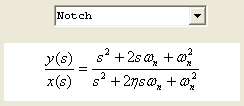
A Notch filter is commonly used in servo system when a sharp mechanical resonance would otherwise cause a system to become unstable. A Notch filter is able to attenuate a very localized range of frequencies. It has a damping factor, η, which effects sharpness or width of the notch. The disadvantage of using a notch filter is some phase lag which tends to decrease phase margin. The introduced phase lag will be less the narrower the notch is (less damping), as well as the distance the notch frequency is above the system bandwidth.
Shown below are two notch filters both at 400 Hz, one with 0.2 damping and the other with 0.4 damping.

Pole-Zero
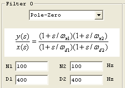
A Pole-Zero filter is commonly used in a lead-lag configuration shown below to shift the phase positive at the 0 db crossover frequency of the system in order to increase phase margin. The filter shown has maximum positive phase of approximately 80 degrees at 200 Hz. This is accomplished by setting the N1,N2 (zeros or numerator frequencies) 2X lower than 200 Hz (100 Hz), and the D1,D2 (poles or denominator frequencies) 2X higher than this (400 Hz). A lead-lag filter (or compensator) may often be used in place of derivative gain (in the PID stage), and has a significant advantage of lower high frequency gain. If a system's gain at high frequencies is increased sufficiently to reach 0 db it may become unstable.

Copy C Code to Clipboard

This pushbutton causes the current z-domain filter coefficients to be copied to the clipboard in a form that may be pasted directly into a KMotion C Program, see also the C Program Screen.
	ch0->iir[0].B0=232.850006;

	ch0->iir[0].B1=-450.471008;

	ch0->iir[0].B2=217.869995;

	ch0->iir[0].A1=1.001990;

	ch0->iir[0].A2=-0.250994;


	ch0->iir[1].B0=1.000000;

	ch0->iir[1].B1=0.000000;

	ch0->iir[1].B2=0.000000;

	ch0->iir[1].A1=0.000000;

	ch0->iir[1].A2=0.000000;


	ch0->iir[2].B0=0.175291;

	ch0->iir[2].B1=0.350583;

	ch0->iir[2].B2=0.175291;

	ch0->iir[2].A1=0.519908;

	ch0->iir[2].A2=-0.221073;
Download

The Download push button downloads the filters for the selected axis (along with all axis configuration and tuning parameters) to the KMotion.


