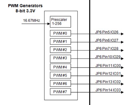
KFLOP has 8 hardware PWMs (Pulse Width Modulators) that output on dedicated KFLOP JP6 pins

There is no direct output support for KFLOP PWMs. A few lines of C Code executing in a loop are required to output the Servo Outputs to the pwms and possibly directions (sometimes referred to as signs) in your required format. This allows flexibility for controlling Mode, Frequency, Range, Polarity, etc... Pre-made examples exist. Often this code can be added to an existing forever loop toward the end of your Initialization C Program.
The PWMs are accessed via a pair of FPGA Registers. The first in the pair is a value 0-255 to set the pulse width. The second register is a single bit enable register. A value of 1 enables the PWM to take control of the Output pin and begin pulsing. The PWM pin must be configured as an output via a SetBitDirection call. A value of 0 disables the PWM and allows the pin to be used as General Purpose IO.
There is also a global pre-scaler to set the frequency of all the PWMs. All PWMs must operate at the same frequency. The pre-scaler divides the 16.67MHz input clock by N+1. Where N is a value of 0-255.
PWM1KHz.c is a simple example to enable a PWM to operate at a fixed period and frequency:
#include "KMotionDef.h"

main()
{
	SetBitDirection(26,1);  // define bit as an output
	FPGA(IO_PWMS_PRESCALE) = 65;  	// divide clock by 65 (1 KHz)
	FPGA(IO_PWMS) = 128;  			// square wave
	FPGA(IO_PWMS+1) = 1;  			// Enable
}
Usually a PWM is used to drive a Full H-Bridge Driver to control the effective voltage to a motor coil. There are two basic modes of operation: Sign/Magnitude and Anti-Phase. With Sign and Magnitude the Sign controls the polarity of voltage (either positive or negative) and the PWM pulse controls the fraction of time the voltage is applied. The voltage is applied for some fraction of the time period and zero volts are applied for the remainder. With Anti-phase there is no Direction Output required. Instead both positive and negative voltages are applied every cycle. Equal amounts of positive and negative voltage results in effectively zero volts. With KFLOP's 8-bit PWMs setting a PWM value of 128 will result in equal positive and negative times.
See the example below "OutputToPWM_sign_mag_single_axis.c"
#include "KMotionDef.h"

// Send Servo Output to PWM as Sign/mag

#define MAXPWM 242
#define DIR_BIT0 30

void OutputSignMag(int ch, int pwm, int dir_bit);

main()
{
	SetBitDirection(26,1);  		// Set bit 26 (PWM 0 as an output)
	SetBitDirection(DIR_BIT0,1);	// Set bit 30 (Direction an output)
	FPGA(IO_PWMS_PRESCALE) = 1;  	// set pwm period to 30 KHz
	FPGA(IO_PWMS+1) = 1;			// enable the PWM

	for (;;)  //loop forever
	{
		WaitNextTimeSlice();
		OutputSignMag(0,0,DIR_BIT0);
	}
}

// put the servo Output to a specified PWM channel
// and direction bit in signed and magnitude mode

void OutputSignMag(int ch, int pwm, int dir_bit)
{
	if (chan[ch].Enable)
	{
		if (chan[ch].Output >= 0)
		{
			if (chan[ch].Output > MAXPWM) // don't go to 100%
				FPGA(IO_PWMS+pwm*2) = MAXPWM;
			else
				FPGA(IO_PWMS+pwm*2) = chan[ch].Output;
			SetBit(dir_bit);
		}
		else
		{
			if (chan[ch].Output < -MAXPWM) // don't go to 100%
				FPGA(IO_PWMS+pwm*2) = MAXPWM;
			else
				FPGA(IO_PWMS+pwm*2) = -chan[ch].Output;
			ClearBit(dir_bit);
		}
	}
	else
	{
		FPGA(IO_PWMS+pwm*2) = 0;  // whenever not enabled put 0% duty cycle
	}
}
See the example below "OutputToPWM.c" written for an anti-phase type of H Bridge drive:
#include "KMotionDef.h"

main()
{
	SetBitDirection(26,1);  	// Set bit 26 (PWM 0 as an output)
	FPGA(IO_PWMS_PRESCALE) = 1;  	// set pwm period to 30 KHz
	FPGA(IO_PWMS+1) = 1;		// enable the PWM

	for (;;)  //loop forever
	{
		WaitNextTimeSlice();
		if (ch0->Enable)
			FPGA(IO_PWMS+0) = ch0->Output + 128;  // +128 converts to anti-phase
		else
			FPGA(IO_PWMS+0) = 128;  // whenever not enabled put 50% duty cycle
	}
}
You might also search the C Programs directory for other PWM examples.