Hi Jose,
Very nice looking board!
The GPIO Inputs are directly connected to an
IC
SN74HC165PWR
They should be very high impedence. I don't know why there would be a problem.
The Opto inputs are a
TLP281-4GBFCT
(or similar)
They have a 10Kohm in series so they work with 24V so they need at least 5V to turn on. They work better with 12 or 24V. How much voltage are you applying?
Regards TK
| Group: DynoMotion |
Message: 7408 |
From: controlesdirecto95 |
Date: 5/2/2013 |
| Subject: Re: Problems |
|
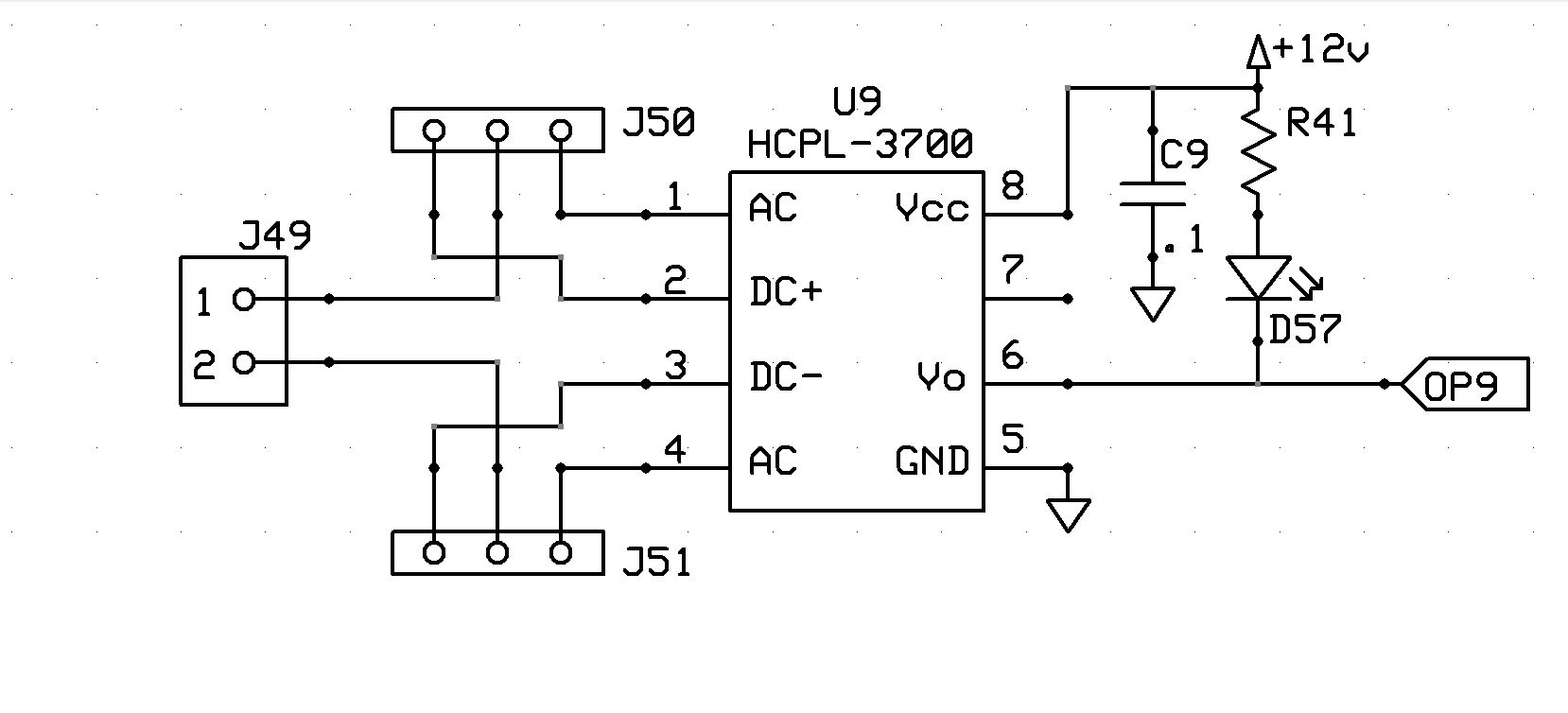
tom,
this is my circuit connected to your board, I use the same to gpioa and
opto inputs, do you know wich is the problem??. all of the gpio is ON
and the opto inputs only work 2-7 please help
regards
jose castaneda
|
|
|
@@attachment@@
|
| Group: DynoMotion |
Message: 7410 |
From: Tom Kerekes |
Date: 5/2/2013 |
| Subject: Re: Problems [1 Attachment] |
Hi Jose, I don't understand. Are you connecting OP9 to a Kanalog 3.3V GPIO pin? Regards TK
| Group: DynoMotion |
Message: 7413 |
From: controlesdirecto95 |
Date: 5/2/2013 |
| Subject: Re: Problems |
| Group: DynoMotion |
Message: 7414 |
From: TK |
Date: 5/2/2013 |
| Subject: Re: Problems |
Hi Jose,
You didn't tell us which type of Kanalog Input.
You can not connect 12V signals to 3.3V Kanalog GPIO inputs. The 3.3V inputs have protection diodes to the 3.3V supply. This will prevent going higher than ~3.8V. So your LED connected to 12V will still see ~8V and always stay on. But actually the signal to Kanalog should change between ~3.8V and ~0.2V and KFLOP should show the change correctly.
It should work if connected to the Kanalog opto inputs depending on how it is wired.
Regards
TK On May 2, 2013, at 9:26 AM, jcf@... wrote:
|
|
| Group: DynoMotion |
Message: 7421 |
From: controlesdirecto95 |
Date: 5/3/2013 |
| Subject: Re: Problems |
|
Hello Tom,
Our board is working now, the problem, the optocoupler damage because I
connect the + in the - and the - in the + and the optocupler damage, now
I install a diode to protect.
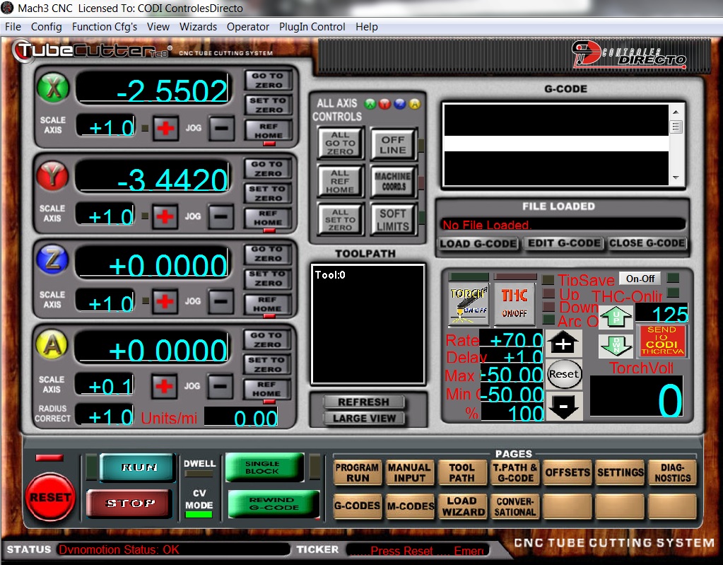
ok, I'm ready to start with mach3, the first I want to turn on and
output and read a input in a lED in mach3.
I think I need to make a script file with code in a button . That's
right??. Or do you can explain me a little bit how mach3 communicate
with kflop.
Regards,
jose Castaneda
|
|
| Group: DynoMotion |
Message: 7423 |
From: Tom Kerekes |
Date: 5/3/2013 |
| Subject: Re: Problems |
Hi Jose,
For just several LEDs I don't think you need any script. You can just assign a Mach3 input to a KFLOP IO . Then use the pre-defined Mach3 OEM LEDs for the Mach3 Inputs. See:
http://www.machsupport.com/MachCustomizeWiki/index.php?title=OEM_LEDs
But otherwise the only way to upload information to Mach3 is through DROs. See:
http://www.dynomotion.com/Help/Mach3Plugin/Mach3DROs.htm
Regards TK
| Group: DynoMotion |
Message: 7424 |
From: controlesdirecto95 |
Date: 5/3/2013 |
| Subject: Re: Problems |
|
Tom,
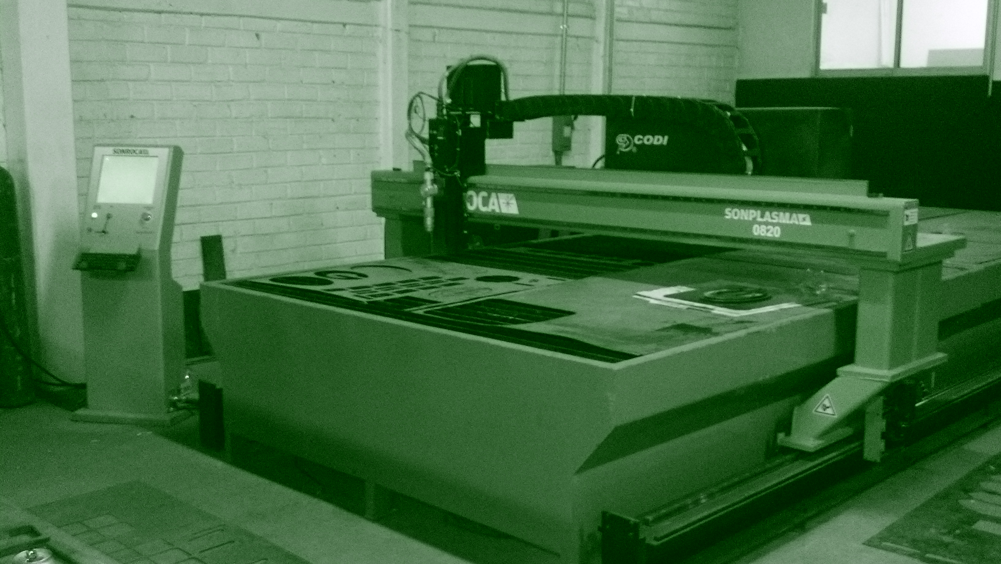
This is my first time with your Kflop, but I think we can install in
our machines. but I need your help to go rapid success with your board
and think to install in our machines.
Do you can tell me how to configure the I/o in mach3 to mach with kflop
the number of port and pin in the configuration page of mach3
regards,
jose castaneda
|
|
|
@@attachment@@
|
| Group: DynoMotion |
Message: 7427 |
From: Tom Kerekes |
Date: 5/3/2013 |
| Subject: Re: Problems [2 Attachments] |
Hi Jose,
The first step is to get a motor to move using KMotion.exe. Have you done this? What type of amplifiers do you have?
Regards TK
| | | | | | | |
![2013-05-01_12-26-16_782[1]-7399.jpg](https://www.dynomotion.com/forum/archive/attachments/2013-05-01_12-26-16_782[1]-7399.jpg)