Konnect - PWM to Analog Example
KFLOP/Kogna+Konnect+Simple Filter Circuit can be used to produce a programmable analog signal. This might be used as a basic Spindle Speed Control Signal if no others are available.
This demonstrates the flexibility of the Konnect Outputs which are Isolated, can sink or source current, fast, medium power, and low impedance
Results
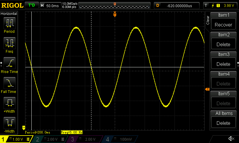
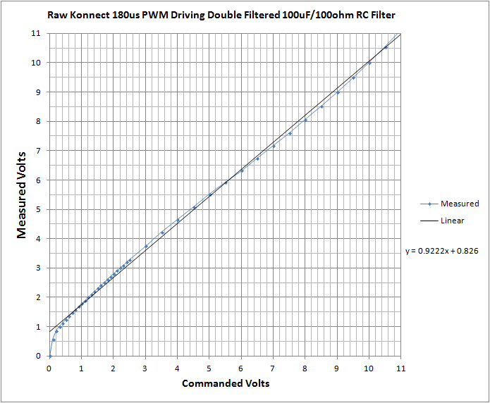
Analog Oscilloscope traces of Analog signals generated by a KFLOP/Kogna Software generated PWM Signal controlling two optically isolated Konnect Outputs that are then passed through a simple low pass filter.
High resolution and response rates easily usable for speed control applications

Square wave to test large signal changes. Significant change in < 25ms

Reasonable linearity. This would require calibration if higher accuracy is needed.

Circuit
Simple cascaded dual low pass filters. Only 5 components. One resistor type and one capacitor type. Component values are not critical (R1 and R2 should be matched).
One Konnect Output charges the capacitors and one output discharges them. Both should not be turned on simultaneously (but no damage will occur if they are as R1+R2 will limit the current).
The relatively low resistance values (100 Ohms) provides low output impedance so that any connected load should have a minimal effect. A load of 10Kohms or higher should work well.
Double filtering provides low output ripple, while still having relatively quick response to changes, uses reasonably small capacitors, even with relatively low PWM rates.
Konnect Outputs can be updated every 180us. So 180us is the basic PWM quantum. This results in ~ 10mV p-p ripple.


Software
This software example simulates how an RC circuit would respond to an applied, switched, high/low voltage.
If the simulated voltage is below the desired output voltage then the output is switched high to charge up the capacitor, otherwise it is switched low to discharge the capacitor.
The same state that is simulated is also sent to the Konnect Outputs to drive the real circuit. The real circuit is a bit more complex but the simple model works reasonably well. The two RC circuits will eventually evolve to the same voltage as the average PWM Voltage in the steady state. Only the transient response will be slightly different. Similarly, somewhat incorrect component values will only affect the transient response. The progra values were adjusted to get the best response.
The #define statements may require changes for your specific circuit and I/O Bit used.
The Vout value is coded to create a sine wave, but more typically the value would be passed in through a global persist variable as a Spindle Speed Setting.
	#include "KMotionDef.h"

	// Enables a Konnect on KFLOP JP4 Aux Port then
	// PWM's two outputs as push-pull drivers such that
	// when low passed filtered with an RC circuit becomes
	// a variable analog source.
	//
	// Configure KFLOP to service Konnect 32 Input 16 output IO board
	// Board address is 0,
	// 16 Outputs are mapped to Virtual IO 48-63 (VirtualBits)
	// 32 Inputs are mapped to Virtual IO 1024-1055 (VirtualBits[0])
	//
	// Attach Service to Aux0 Port (KFLOP JP4) instead of standard Aux1 Port (KFLOP JP6)
	//

	void ServiceKonnectPWM(void);

	double T,T0=0;
	float Vout=0.0;		// desired voltage

	main()
	{
		InitAux();
		AddKonnect_Aux0(0,&VirtualBits,VirtualBitsEx);

		for(;;)
		{
			T=WaitNextTimeSlice();
			ServiceKonnectPWM();

			// Fixed
			// 		Vout = 0.1;

			//Generate a 5 Hz 3V Sine Wave
			Vout = 3.0f*sin(T * TWO_PI * 5.0) + 5.0;

			//Generate a Saw Tooth wave
			// 		Vout = 2 + 6.0* (5.0*T - ((int)(5.0*T)));

			//Generate a 5 Hz Square wave
			// 		Vout = (5.0*T - ((int)(5.0*T))) > 0.5 ? 8 : 2;
		 }
	}

	#define C 0.00029f	// 1000uF
	#define R 100.0f	// 100 ohms
	#define Vcc 11.230f // supply voltage
	#define HIGH_BIT 62 // This output drives Cap high
	#define LOW_BIT 63	// This output drives Cap low

	void ServiceKonnectPWM(void)
	{
		static int FirstTime=TRUE;
		static float Vc=0.0f;
		static double T0;
		static int State;
		double T=Time_sec();

		if (FirstTime)
		{
			FirstTime=FALSE;
			T0=T;
 			State=0;
		}
		else
 		{
			float V,I;

			// Compute Voltage applied to Cap
			V=Vcc*State;

			// Compute current
			I=(V-Vc)/R;

			// Compute new Cap Voltage
			Vc += I/C*(T-T0);

			// determine next state

 			if (Vc > Vout)
 			{
 				ClearBit(HIGH_BIT);
				SetBit(LOW_BIT);
				State=0;
			}
			else
			{
				ClearBit(LOW_BIT);
				SetBit(HIGH_BIT);
				State=1;
			}

			T0=T;	// save time when applied
			}
	}