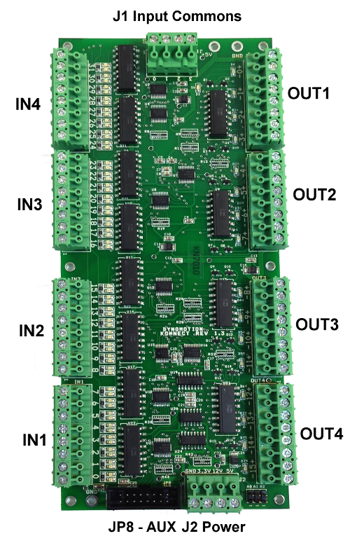
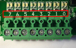
Konnect - Connector Pinouts

Konnect JP8 Aux Bus Connection to KFLOP/Kogna JP6 or JP4

JP8 provides all internal signal and power connections to KFLOP/Kogna by being connected to either JP4 or JP6. See note below for how to write the code depending on which connector is used. This 16 pin ribbon connection should be as short as possible to avoid noise and crosstalk as the cable forms a high speed communication link. The Aux Bus supports multiple boards connected to the same cable. In most cases the specifics of the Aux Bus will be handled internally by KFLOP/Kogna and no knowledge of the signals will be required for use.
The 8 data bits (DB0-DB7) are bi-directional. CLKIN and STARTIN allow a board to be selected by the address placed on the bus, and then a fixed sequence of 8-bit writes (2) and reads (5) can be performed using the CLKIN signal.
| Pin | KFLOP/Kogna Name | Konnect Name |
|---|---|---|
| 1 | VDD5 | VDD5 |
| 2 | VDD12 | VDD12 |
| 3 | VDD33 | VDD33 |
| 4 | RESET# | RESET# |
| 5 | IO26 | DB0 |
| 6 | IO27 | DB1 |
| 7 | IO28 | DB2 |
| 8 | GND | GND |
| 9 | GND | GND |
| 10 | IO29 | DB3 |
| 11 | IO30 | DB4 |
| 12 | IO31 | DB5 |
| 13 | IO32 | DB6 |
| 14 | IO33 | DB7 |
| 15 | IO34 | CLKIN |
| 16 | IO35 | STARTIN |
J2 Konnect Power

The power signals from KFLOP's/Kogna's Aux Bus are available on the J2 terminals. It is not normally necessary to apply power to these terminals as power is supplied from KFLOP/Kogna through the JP8 connector. For multiple boards it may be desirable to apply additional higher gauge power and GND connections between boards. Note the Signal labeled 12V is connected to the KFLOP/Kogna 12V signal but may not be necessarily 12V. KFLOP/Kogna and Konnect do not require or use the 12V signal but only pass the signal through the various connectors. Disk Drive Power Supplies usually supply +12V into KFLOP/Kogna JR1 Pin 1. Also note that if any of these supply voltages are used for the Inputs or outputs then the Input wiring will not be isolated from KFLOP/Kogna.
It is possible to supply +5V power to KFLOP/Kogna through these terminals if the power consumption on KFLOP is less than 1 Amp and the ribbon cable connection is short (several inches or less).
Optically isolated Inputs

Individual Inputs (1 of 4 shown)

Input Bank Commons
Konnect's 32 optically isolated inputs are grouped into 4 independent Banks of 8 inputs. This allows any Bank to be used with either sourcing or sinking signals. However all inputs in the same bank share the same common and must operate in the same mode. The 4 independent Banks also allow different supply voltages and supply isolation to be used for each Bank. 24V is the preferred input voltage and will draw (24V - 1.4 - 1.4)/4K ~5ma of current.
Konnect's 32 optically isolated inputs can be driven from a +/- 4.75V to a +/-25V signal. Less than 2V should be applied to ensure the input is off. One of the 32 input circuits is shown below. The input consists of a AC type of Optocoupler in series with an LED indicator in series with a 4Kohm resistor. The AC type of input allows the common to be connected to either the Positive or Negative Supply voltage so that either sinking or sourcing outputs can be used (current can flow either direction to activate the input).

External Wiring would typically be arranged such as:

Opto Isolated Outputs

Outputs (1 of 4 shown)
Each of the 16 Optically Isolated Outputs is completely isolated with a + and - terminal. When active the output passes current from the + to - terminals much like a relay contact would.
The Outputs are capable of driving medium power devices such as relay coils. Loads up to 30V @ 250ma may be driven.
The internal Konnect Output Circuitry is shown below which converts a photo transistor output to darlington transistor output. The 220Ohm resistor allows the output have a low on voltage for low currents before the transistor turns on. This allows the output to drive low current circuits with a smaller on voltage (2ma @ < 0.6V). For example LVTTL/TTL inputs require less than 0.8V to guarantee a low input. At higher currents Q1 becomes active and keeps the on voltage drop below 0.9V at 0.25A. Switching 0.25A at 24V allows loads up to 6W to be driven.

A typical wiring diagram driving 24V relays. Because of the less than 0.9V drop on the Konnect outputs the load will be driven with more than 23.1V.

Board Address Selection Jumpers

The KFLOP's/Kogna's Auxiliary Port works as a Bus where multiple boards can be connected to the same Port. Each board has an address so it can be selected as active. For a single Konnect board in the system removing all Jumpers will configure the Konnect Board Address as zero. If multiple boards are to be used set each board to an unique address.
| A0 | A1 | A2 | Address |
|---|---|---|---|
| Removed | Removed | Removed | 0 |
| Installed | Removed | Removed | 1 |
| Removed | Installed | Removed | 2 |
| Installed | Installed | Removed | 3 |
| Removed | Removed | Installed | 4 |
| Installed | Removed | Installed | 5 |
| Removed | Installed | Installed | 6 |
| Installed | Installed | Installed | 7 |
KFLOP/Kogna can be configured to service each Konnect Board using the AddKonnect function. The first parameter is the board address. The second parameter is the address of where KFLOP/Kogna should obtain data to send to Konnect's 16 Outputs. The 3rd Parameter the address of where KFLOP/Kogna should place the data received from Konnects 32 Inputs.
In most cases the addresses will be KFLOP/Kogna Virtual I/O bit locations. KFLOP/Kogna has two sets of Virtual I/O Bits, standard and extended. The standard consists of 16 Bits in VirtualBits, and the Extended consist of 1024 Bits in VirtualBitsEx[32].
The code below configures KFLOP/Kogna to service 4 Konnect Boards (192 IO bits):
	InitAux();
	AddKonnect(0,&VirtualBits,VirtualBitsEx);
	AddKonnect(1,VirtualBitsEx+1,VirtualBitsEx+2);
	AddKonnect(2,VirtualBitsEx+3,VirtualBitsEx+4);
	AddKonnect(3,VirtualBitsEx+5,VirtualBitsEx+6);
Board 0 has Output Bits mapped to 48-63 and Input Bits Mapped to 1024-1055.
Board 1 has Output Bits mapped to 1056-1071 and Input Bits Mapped to 1088-1119.
Board 2 has Output Bits mapped to 1120-1135 and Input Bits Mapped to 1152-1183.
Board 3 has Output Bits mapped to 1184-1199 and Input Bits Mapped to 1216-1247.
Typical IO Mapping for Standard Single Konnect
Note: Konnect(s) can be connected to JP6 (Aux1) :
	InitAux();
	AddKonnect(0,&VirtualBits,VirtualBitsEx);
or JP4 (Aux0) but use:
	InitAux();
AddKonnect_Aux0(0,&VirtualBits,VirtualBitsEx);| Outputs | Virtual IO Number |
|---|---|
| 0 | 48 |
| 1 | 49 |
| 2 | 50 |
| 3 | 51 |
| 4 | 52 |
| 5 | 53 |
| 6 | 54 |
| 7 | 55 |
| 8 | 56 |
| 9 | 57 |
| 10 | 58 |
| 11 | 59 |
| 12 | 60 |
| 13 | 61 |
| 14 | 62 |
| 15 | 63 |
| Inputs | Virtual IO Number |
|---|---|
| 0 | 1024 |
| 1 | 1025 |
| 2 | 1026 |
| 3 | 1027 |
| 4 | 1028 |
| 5 | 1029 |
| 6 | 1030 |
| 7 | 1031 |
| 8 | 1032 |
| 9 | 1033 |
| 10 | 1034 |
| 11 | 1035 |
| 12 | 1036 |
| 13 | 1037 |
| 14 | 1038 |
| 15 | 1039 |
| 16 | 1040 |
| 17 | 1041 |
| 18 | 1042 |
| 19 | 1043 |
| 20 | 1044 |
| 21 | 1045 |
| 22 | 1046 |
| 23 | 1047 |
| 24 | 1048 |
| 25 | 1049 |
| 26 | 1050 |
| 27 | 1051 |
| 28 | 1052 |
| 29 | 1053 |
| 30 | 1054 |
| 31 | 1055 |