Configuring Closed Loop Step and Direction Outputs
The Closed Loop Stepper Mode works much the same as open loop Step and Direction Output Mode except there is also an error feedback correction term. In fact, if the gains of the correction term (PIDs) are set to zero then the mode will behave the same as an open loop Step Direction Mode. This mode is much easier to “tune” than a stepper driven as a brushless motor and unlike a brushless motor there are no commutation issues. A good application for this mode is a stepper with linear glass scales. The main feature is the position feed forward with fixed gain of 1.0. See the flow diagram below. Without any correction it behaves just like a stepper. As correction gains are added, corrections for drift, friction, load forces, or even a miss step are made. One disadvantage is that the motor can still stall. After the stall and after the motion stops the servo loop could then gradually correct the position which could be of value in some applications.

To Configure an axis a a Closed Loop Servo select "CL Step" as the output mode for the axis as shown below. Any input mode may be used as position feedback, but the most common is a quadrature encoder either on the motor shaft or as a linear glass scale.
Note that an Input gain of 1.25 is used in this example. This was calculated from the ratio of the number of μSteps/rev to the number of encoder counts/rev. (A micro stepper amplifier set to 50 microsteps/full setp and a standard stepper motor with 200 full steps/rev will have 10,000 μSteps/rev, a rotary encoder with 2000 lines/rev will profuce 8000 quadrature counts/rev, 10000/8000 = 1.25). The raw axis units will be in μSteps.
Max Following Error may be used to trip an axis disable when exceeded.

Important PID parameters are shown below circled in red. The I (Integrator) gain of 0.01 is probably the most important. Your system may require more or less. Too much and the system may over shoot or become unstable (oscillate). Too little and corrections will be made slowly. Because we are measure the position and also commanding a position Integrator control works well. An integrator will ramp the output at a rate proportional to the amount of the error. This "slowing as we get closer" will result in an exponential curve approaching the target. Backlash, friction, delays, and other factors will eventually cause the system to overshoot and become unstable with too much gain.
Max limits may also be useful for limiting the correction. In this example the limits are set to large values. Limiting the max error to a small value will limit the maximum slew rate of the Integrator. Max Output and Max Integrator are similar for an Integrator only compensator and will limit the maximum amount of correction that can be made.

A 2nd order Low Pass Filter is also used in this example to make the system more stable by reducing high frequency corrections. Note a cutoff frequency of 100Hz with Q 1.4 is used. After specifying the filter the Compute Button must be pressed to compute the Z domain IIR Coeffiecients that are downloaded and used by KFlop.

Test Mechanism with Size 34 Stepper with encoder connected to a Dummy Load.

Test Move of a Size34 Stepper with 50 usteps/full step forward and backward at 4000sps
With PID gain zero (no correction). Note encoder shows errors of ~100uSteps
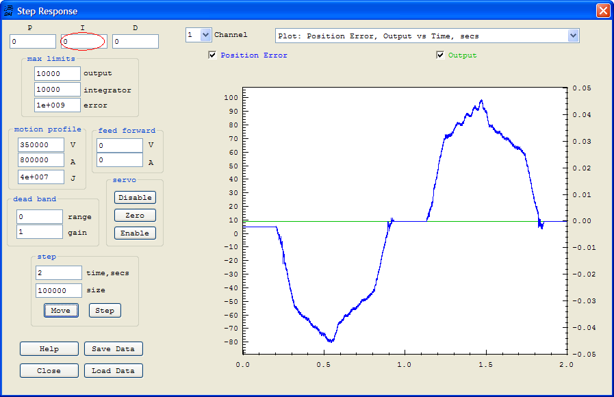
Integrator gain now set at 0.01. Also 2nd Order 100Hz Low Pass Filter Q=1.4 used
Note error is reduced. Blue plot is position error, green is the Output (correction offset)

A Bode Plot of the Compensator PID + LP Filter response. I=0.010 and 2nd order Low Pass 100Hz @ Q=1.4. Red plot is Magnitude.
Note that errors less than about 20 Hz will be corrected. Correction gain drops below 1 (0db) at higher frequencies.
