Driving Hobby Servos
From Dynomotion
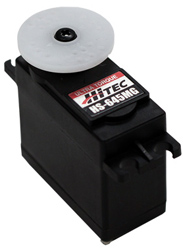
Hobby RC Servo modules like this can be controlled from KFLOP.
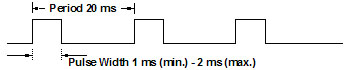
Most Servo Modules require a 1-2ms pulse at 50Hz to command their position.
This is somewhat difficult to generate with normal PWM generators as high Time resolution is required at a slow rate. KFLOP Hardware PWM generators have a minimum frequency of 254Hz.
A KFLOP User C Program can be used to enable and disable a PWM generator in a way that one pulse is output only every N PWM cycles. PWM gernerator #1 is sacrificed to generate a fixed long PWM pulse that the C Program can monitor to count cycles as well as determine when the next PWM cycle for all the PWM generators will begin.
1 2 3 4 5 6 7 8 9 10 11 12 13 14 15 16 17 18 19 20 21 22 23 24 25 26 27 28 29 30 31 32 33 34 35 36 37 38 39 40 41 42 43 44 45 46 47 48 49 50 51 52 53 54 55 56 57 58 59 60 61 62 63 64 65 66 67 68 69 70 71 72 73 74 75 76 | #include "KMotionDef.h"void ServiceHobbyPWM(void);int ncycles, v1, v2;main(){ int LowClocks, scaler=150; float PWMPeriod, BaseFreq=16.6667e6, PulseGap=20e-3, SafetyTime=200e-6; // Set base PWM to be high for entire time less 200us LowClocks = SafetyTime * BaseFreq / scaler; PWMPeriod = 256.0*scaler/BaseFreq; ncycles = PulseGap/PWMPeriod; printf("PWM Period = %fus\n", PWMPeriod*1e6); printf("Low Clocks = %d\n", LowClocks); printf("Skip Cycles = %d\n", ncycles); SetBitDirection(26,1); // define bit as an output ClearBit(26); SetBitDirection(27,1); // define bit as an output ClearBit(27); SetBitDirection(28,1); // define bit as an output ClearBit(28); FPGA(IO_PWMS_PRESCALE) = scaler; // divide clock by 256 (250Hz) FPGA(IO_PWMS) = 255-LowClocks; // Mostly high pulse FPGA(IO_PWMS+1) = 1; // Enable ClearBit(26); v1 = 800e-6 * BaseFreq / scaler; // set Pulse time v2 = 1700e-6 * BaseFreq / scaler; // set Pulse time printf("PWM settings v1 = %d v2 = %d\n", v1,v2); for (;;) { ServiceHobbyPWM(); }}void ServiceHobbyPWM(void){ static int i=0; static WaitLevel=0; if (!WaitLevel) // waiting for low? { if (!ReadBit(26)) // yes is it low? { WaitLevel=1; // yes, change state if (++i == ncycles) // count mostly high pulses, special cycle? { FPGA(IO_PWMS+2) = v1; // Pulse size FPGA(IO_PWMS+3) = 1; // Enable FPGA(IO_PWMS+4) = v2; // Pulse size FPGA(IO_PWMS+5) = 1; // Enable i=0; } else { FPGA(IO_PWMS+3) = 0; // Disable FPGA(IO_PWMS+5) = 0; // Disable } } } else { if (ReadBit(26)) // no, waiting for high, is it high? { WaitLevel=0; // yes, change state } }} |
The code above prints this:
PWM Period = 2303.995425us
Low Clocks = 22
Skip Cycles = 8
PWM settings v1 = 88 v2 = 188
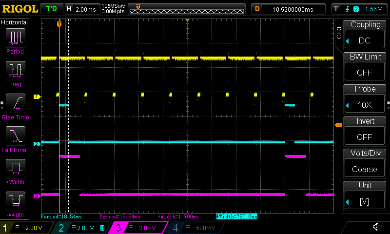
It generates the timing shown below. Note the yellow trace is the reference PWM used by the C Program to count the cycles. Two PWM pulses are emitted every 8 cycles. The cyan trace shows a pulse width of 780us (specified in the program to be 800us) with a period of 18.5ms. The magenta trace shows a pulse width of 1.7ms (specified in the program to be 1700us) with a period of 18.5ms.