Trajectory Planner Corner Rounding Settings
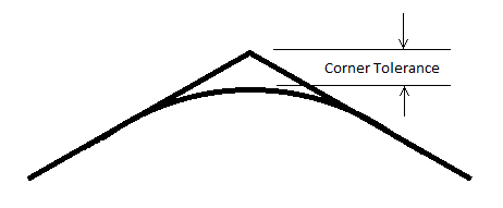
The KMotionCNC Trajectory planner contains two parameters (Facet Angle and Corner Tolerance) that can be used to smooth paths generated by line segments in the GCode. Although shown below as 2D paths this smoothing applies for 3D paths as well. Standard GCode and many CAD systems do not support arcs in arbitrary 3D space so small line segments are typically used to define the 3D path. Facet Angles in the original GCode data that are less than the specified Break Angle (which are considered "small" and will not cause a motion stop) will be re-faceted with smaller line segments along a curve to have Facet Angles smaller than the specified amount. The new line segments will be placed along the largest arc that will not deviate more than the specified Corner Tolerance or consume more than 1/2 of the segment length. If no Corner Rounding is desired the Corner Tolerance can be set to zero.


Shown below is an example motion path where the bottom right arc is formed by 30 line segments. Normally a simple arc could be specified but for test purposes it was created with 30 3 degree angle facets forming the 90 degree turn. The tests below were performed simulating a fairly high performance system with 30 in/sec2 acceleration in both X and Y. The Gcode used can be downloaded here.
Here is the path Overview.

Notice the circled region of the path looks smooth, but when zooming in as shown below the 3-degree angle facets are just barely visible. This resolution is typically used to provide a reasonably smooth path without making the file size abnormally large.

In the plot below the Corner Rounding is enabled and the facets are now reduced in size and form 0.5 degree angles that can now no longer be seen.

To see more clearly the improvement the X Axis motion was captured in real-time (180us sample rate) and plotted. From the position the Velocity and Acceleration were also computed and plotted.
First the original captured motion X axis position, velocity, and acceleration vs. time through the original 3-degree facets with no corner rounding.
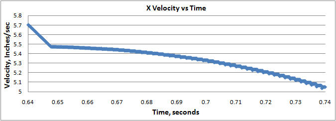
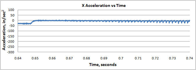
Note that the velocity plot has an odd shape for several reasons. At constant velocity the facet angle change causes the x velocity to drop while the y velocity increases, but since we are accelerating through the curve (because a more diagonal direction can make use of the increased (combined) acceleration of both axes) the velocity ramps up at the max acceleration toward the beginning of each facet. The programmed feed rate is 400ipm (6.67ips) but the speed is acceleration limited by the curvature of the path, hence the deceleration to ~ 5.5ips on the left as we enter the curve.


Now using the Trajectory Planner settings shown below. Notice the velocity is much smoother and the Acceleration is less Jerky.


For still further motion smoothing an additional KFLOP feature can be used. A low pass filter can be applied to the output of the coordinated motion path.
The Low Pass Filter will be applied to all axes of coordinated motion (up to 8) by setting the KLP coefficient within KFLOP. Currently a C Program must be used to set this global parameter.
To compute an appropriate coefficient from a time constant Tau in seconds use the formula KLP = exp(-TIMEBASE/Tau) as shown below
	#include "KMotionDef.h"
	main()
	{
		double Tau = 0.001; // seconds for Low Pass Filter Time Constant
		KLP = exp(-TIMEBASE/Tau);
		printf("Tau=%f KLP=%f\n",Tau,KLP);
	}
Note the Velocity and Acceleration plots are even smoother. A low pass time constant Tau = 1 millisecond was used.


The disadvantage associated with low pass filtering of the trajectory is a potential lag in the commanded positions which may cause small path errors. The plots shown below show that a Low Pass Filter setting of 1 millisecond will be insignificant for most systems. A nearly worst case 90-degree angle with max deceleration on the X axis, followed by max acceleration on the Y axis are shown below.
The first case is captured with no Low Pass Filtering. Note a perfectly square corner. Each tick mark shows a captured 180us sample point.

The case below is with 1 millisecond of filtering with a path error of ~ 0.01 mil (0.25um)

The case below is with 3 milliseconds of filtering with a path error of ~ 0.1 mil (2.5um)

Because the Low Pass Smoothing introduces a small position lag the very end of the smoothed path will not be completed when the coordinated path is completed. To complete the path the final position and velocity of each of the coordinated axes are used to calculate a Cubic Spline to complete the final small motion. The Cubic Spline allows continuous velocity from the end of the smoothed path to the target position in a manner where the velocity also reaches zero at the target position. A Time duration of the Cubic Spline set at 2xTau of the low pass filter provides a relatively constant deceleration to the Target.
